1. THERMAL INSULATION PROPERTIES OF THE COATING
Liquid ceramic thermal insulation coating Armor is a liquid composition based on water. It consists of microscopic ceramic vacuumed spheres, pigmenting, inhibiting and antiperene additives. The main component is a polymer latex composition. Hollow microspheres (ceramic) are dispersed in the composition. The sizes of microspheres are 0.01...0.5 mm.
This thermal insulation coating Armor is used for corrosion protection, thermal insulation, protection from ultraviolet radiation, and also has dielectric properties. The thickness of one layer of Armor coating is 0.4...0.5 mm. Advertising and explanatory materials report that hollow microspheres are sparse.
When used in heat supply systems, the most important thermal engineering properties of thermal insulation materials are manufacturability, durability, low coefficient of thermal conductivity, environmental safety.
The technology of applying liquid thermal insulation to pipelines and other surfaces is simple and affordable. Its feature is the ability to cover surfaces of complex configurations, while the presence of insulation does not create inconveniences during maintenance and repair. When using conventional thermal insulation materials in heating networks, uninsulated or partially isolated areas remain, the presence of which leads to additional heat losses. Liquid thermal insulation coating Armor can provide a significant reduction in additional heat losses. If it were possible to reduce these heat losses at least by half, it would give fuel savings of 8.3% (taking into account the efficiency of the boiler 0.9).
Taking into account the totality of the positive properties of liquid thermal insulation Armor, it is also advisable to use it for thermal insulation of heat pipelines and other elements in enclosed spaces (boiler houses, pumping substations, TRS, etc.). In addition to thermal insulation, the coating will reduce the dimensions of heat-insulated elements, provide ease of maintenance, improve the ecology and design of premises.
The durability of liquid ceramic thermal insulation Armor is at least 10 years.Accelerated climatic tests of the coating on concrete and metal surfaces allowed us to conclude that the preservation of the protective and decorative properties of the coating corresponds to at least 10 years in temperate and moderately cold climatic regions.
The durability of mineral wool insulation widely used in thermal networks is estimated at 5-6 years. However, this insulation quickly loses its potential thermal insulation properties due to humidification. Under the influence of moisture, the insulation layer loses its original configuration (especially when laying overhead heat pipelines), the effective coefficient of thermal conductivity increases significantly, as a result of which heat losses to the environment increase. In contrast, liquid thermal insulation is not moistened, retains its original shape, dimensions, thermal insulation properties. For these reasons, during the entire service life, the coating must provide initial heat loss. In this regard, it would be advisable to use a coating for thermal insulation of aboveground heat pipelines.
The most important indicator of the thermal insulation material is the coefficient of thermal conductivity equal to 0.0012 W / m ° C. That is, liquid thermal insulation coatings are much superior to known thermal insulation materials.
2. MEASUREMENT CAPABILITIES OF COVERAGE PERFORMANCE INDICATORS
In heat supply systems, the use of thermal insulation allows solving two main tasks: ensuring a safe temperature on the outer surface of the heat pipeline for a person, as well as reducing heat loss to an acceptable level. It is impossible to completely eliminate heat losses to the environment, but it is possible to reduce it by using more efficient insulation, or by increasing the insulation thickness. Both require additional costs. For heat pipelines, an increase in insulation thickness leads to a decrease in heat losses only up to a certain limit, after which heat losses increase with increasing insulation thickness. Therefore, from the point of view of heat losses, it is necessary to choose the “golden mean”, comparing the costs of insulation with possible heat losses.
With regard to the temperature of the outer surface of heat pipelines and other equipment of heating networks, modern requirements are quite definite. These requirements are that upon contact with the surface of the skin, a person should not get burned. It is believed that if a person's skin comes into contact with a surface with a temperature of 60 ° C for 5 seconds, a person will receive a first-degree burn (without damage to internal tissues). When calculating thermal insulation, the maximum surface temperatures in working areas should be 45 ° C (indoors) and 55 ° C (outdoors).
It is also known that the temperature effect on the human skin depends not only on the temperature, but also on the properties of the medium or surface with which the skin comes into contact. On this occasion, we can recall the difference from contact with metal and wood in a good frost. Lovers of steam raise the temperature in the steam room to 60 ° C and above and do not get burns. It will be even more convincing to take a coin with you to the steam room and feel the difference from touching it and a wooden shelf. In the examples given, measuring instruments are not needed to confirm that the temperatures of different surfaces are the same.The above temperature of 55 °C is set for the metal cover layer, and for other surfaces the temperature is 60 °C.
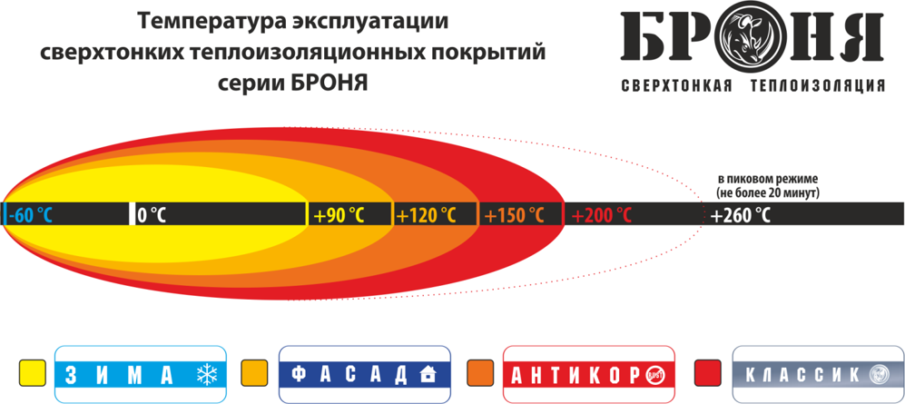
Liquid ceramic thermal insulation coating Armor has unique properties. Uniqueness also applies to the effects on human skin. Simple experiments have been carried out to verify this. Thus, in the course of research it was found that the surface temperature of the coating is 100 ° C safe for humans (at least 5 seconds of contact), and at the surface temperature of the coating 175 ° C, the water on it begins to boil.
Similar experiments were also carried out. An electric furnace was used, on the flat surface of the heating element of which an ultra-thin thermal insulation coating of Armor was applied. The surface temperature of the coating was measured using a thermocouple complete with DT-838 (the characteristics of the device are given below). At different temperatures, the time of contact of the palm with the surface was determined, during which there were no unpleasant sensations. The average contact time for three people is shown in Table 1.
Table 1 - Results of experiments to determine the safe temperature on the coating surface;
| Coating surface temperature,°C | The time of contact of the palm with the surface without unpleasant sensations, with |
|---|---|
| 60 | 30 or more |
| 70 | 30 or more |
| 90 | 14 |
| 100 | 8 |
| 115 | 5 |
According to Table 1, the temperature on the surface of the coating is 90 °C (with some margin), which is safe for the human skin.
Using the same electric furnace, it was found that the water on the surface of the coating begins to boil at a temperature of 170 ...175 ° C. To set this temperature more precisely, it is necessary to more clearly determine the signs by which it is necessary to determine the beginning of boiling. In this case, such a task was not set, and the moment of intensive formation of steam bubbles in the water, which were clearly visible through a magnifying glass, was taken as the beginning of boiling.
Specialists used a graph to assess the safe temperature on the coating surface, on one axis of which the temperature of the metal surface is deposited, and on the other – the temperature on the coating surface. According to this graph, for example, the temperature on the coating surface of 80 ° C is safe for humans (which corresponds to a temperature of 55 ° C on a metal surface).
Regardless of the results of the conducted research, the performance indicators of thermal insulation coatings in practice should be determined by measurements. Imagine that there is a conventional thermal insulation on the heat pipe with a cover layer of roofing material or plastic. How to measure the temperature of the outer surface? Contact measurement methods are not applicable according to theory, since it is impossible to ensure reliable contact of the surface with the temperature sensor. With a metal cover layer about 0.5...1 mm thick, the situation is no better. What can be offered in this case to ensure contact is hardly suitable for use in production conditions. Contactless methods and measuring instruments remain.
Specialists carried out a series of measurements on a full-scale object using the instruments at their disposal.
The object is a water heat pipe with a diameter of 600 mm (the outer diameter is 630 mm, the inner diameter is 612 mm), located in the room of a pumping substation. The pipeline is insulated with mineral wool wrapped with a steel mesh, outside of which a layer of heat-insulating plaster with a thickness of 2...3 mm is applied to the canvas. The total thickness of the insulation layer is 55 mm. There are air gaps of variable height between the layers. Two sections of the heat pipeline with a length of about 0.8 m are released from insulation, one of them is cleaned and left without insulation, the second section is coated with a 1.6 mm thick armor insulation coating. The measurements were carried out on a section of non-insulated pipeline, on a section with existing insulation and on a section with Armor coating.
The water temperature was measured by a standard resistance thermal converter installed in the pipeline, connected to an automatic KSM-2 bridge with a record of readings on a diagram tape. Insulated water tanks were installed at each of the sites, the water temperature in each tank was recorded on KSM-2. The data of such measurements can be used for an approximate comparative assessment of the effectiveness of different thermal insulation.
Various instruments were used for measurements:
- heat flux density meter IPP-2 complete with heat flux density probe PTP-9.9P (manufacturer - Exis CJSC, Moscow; measurement limits 10...9999 W/m2, permissible reduced measurement error ± 5%, conversion factor 73.3 W/(m2 *mV));
- SUR-25 thermometer (manufactured in the USA, measurement limits -20...+120 0C, permissible reduced measurement error ± 2%, the sensing element is a calibrated bimetallic plate);
- digital multifunctional meter (Elcometr) 319 complete with a thermocouple (measurement limits -20...200 0C, temperature measurement error is ± 0.5 0C);
- infrared thermometer "Fluke 561" (manufacturer - "Fluke Corporacion", China; measurement limits -40...+550 0C; measurement error is ± 1% of the measured value or ± 1 0C; spectral range - 8... 14 microns).
Surface temperatures were also assessed by touch. The human skin is a good thermal sensor. The temperature of 36 ° C is determined accurately enough by touch. The temperature of 55 °C is less accurately but reliably determined. The skin tolerates this temperature for a long time without unpleasant sensations, but it feels like this is the limit above which the contact time will have to be limited. On these two reliable reference points, you can build a temperature scale and, after some training, more or less accurately determine the temperature (no higher than 60 ° C).
The most significant results (averaged data) of the measurements carried out when the largest number of devices were used, and the water temperature was the highest during the heating period, are shown in Table 2.
To analyze and evaluate the measurement results, calculations were also performed based on known dependencies for heat transfer through a cylindrical wall.
The heat flux density was determined by the formula
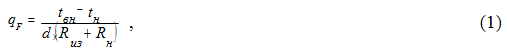
where tn , tn are the temperatures of the water in the pipeline and the outside air, respectively; d is the diameter for which the value of Qf is determined, Rn , Rn are the thermal resistances, respectively, of thermal insulation and heat transfer to the ambient air.
Table 2 - Averaged measurement results on various sections of the heat pipeline (water temperature in the pipeline 92 °C, indoor air temperature 18 °C)
| Measured value | Measuring tool | The value of the measured value for sections of the heat pipeline | ||
|---|---|---|---|---|
| non-insulated heat pipe | existing thermal insulation | Armor coating | ||
| Outdoor surface temperature,°C | Fluke 561 | 87,9 | 39,7 | 60,7 |
| SUR-25 | 74 | 39* | 39* | |
| DT-838 | 85 | 40 | 38 | |
| By touch | >60 | ≈36 | ≈40 | |
| Heat flux density, W/m2 | IPP-2 | 1389 | 306 | 409 |
| Linear heat flux density, W/m (recalculated by heat flux density) | - | 2788 | 711 | 813 |
The formula (1) does not take into account the thermal resistances of heat transfer from water to the inner surface of the pipeline and the pipeline wall. These values are small compared to Rh and Rh, so they are neglected in most cases when calculating heat pipelines.
The values of thermal resistances were calculated according to the formulas
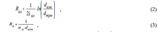
where λiz is the coefficient of thermal conductivity of thermal insulation; Dtrn, Dizn are the outer diameters of the pipeline and insulation, respectively; h is the coefficient of heat transfer from the outer surface of the insulation to the surrounding air.
The linear heat flux density was determined by the formula

The temperatures of the outer surface of the insulation were determined by the formula
The following values were used for calculations:
- Dtrn = 630 mm;
-
- for the existing insulation described above, the thermal conductivity coefficient is difficult to determine. For mineral wool, the values of λ are 0.04...0.05 W/(m *K), for asbestos cement and lime plasters, λ= 0.4...0.7 W/(m *K). The metal mesh as part of the insulation layer increases the resulting pressure, and the existing air gaps decrease. It is very difficult to assess the degree of contact of the layers. For such insulation, the value of λ can be estimated at the level of 0.15 ... 0.25 W/ (m * K). For calculations accepted = 0.2; = 55 mm; = 740 mm. It is clear that an approximate estimate of λiz will also give approximate calculation results;
- for liquid thermal insulation, armor is accepted: = 1.6 mm; diz= 633.2 mm; λiz= 0.001 W/(m *K);
-for surfaces with a low radiation coefficient, take = 6, with a high radiation coefficient - = 11 W/(m2 *K) (for rooms). It is difficult to estimate the values of the radiation coefficients for the surfaces under consideration, but nevertheless the coating should be attributed to surfaces with a low radiation coefficient, and the surfaces of the non-insulated pipeline and the existing insulation are clearly gray. In addition, for an uninsulated pipeline, the convective component should be significantly higher than for the other two surfaces due to the higher surface temperature. That is, the value for a non-insulated pipeline should be greater than 11 W/(m2*K), but not as large as in the open air (29 W/(m2*K). Taking into account the above, it is accepted: for coating = 6 W/(m2*K); for existing insulation = 8 W/(m2*K); for non-insulated pipeline = 20 W/(m2*K).
The calculation results are shown in Table 3.
The analysis of the measurement and calculation results shows the following. There is no reason to doubt the results of measuring the temperatures of tn and tn (92°C and 18°With respectively). Temperature measurements using DT-838 are also evaluated as reliable with some explanations. These temperatures are not the temperatures of the surfaces, since reliable thermal contact of the junction with the surfaces was not provided. The diameter of the working junction was about 0.5 mm. Therefore, the measured temperature should be something between the surface temperature and the temperature in the boundary layer with a thickness of about 0.5 mm. In addition, there is Table 3 - The results of the calculation of parameters for various sections of the heat pipeline
| Value designation | Unit of measurement | Calculated values of values for sections of the heat pipeline | |||
|---|---|---|---|---|---|
| uninsulated pipeline | existing insulation | Armor Coating | |||
| λiz=0.001 | λiz=0.004 | ||||
| Riz | (m ×K)/Tue | - | 0,4023 | 2,533 | 0,6333 |
| Rn | 0,07936 | 0,1689 | 0,3632 | 0,2632 | |
| Qf | W/m2 | 1480 | 175,1 | 41,2 | 130,4 |
| qi | W/m | 2922 | 406,8 | 81,9 | 259,2 |
| tizn | °C | - | 39,9 | 25,9 | 39,1 |
additional thermal resistance at the place of loose contact of the working junction with the surface. As a result, the DT-838 shows a 3.3% lower temperature on the non–insulated pipeline than the Fluke 561, and a 4.3% lower temperature on the existing insulation. However, on the Armor coating, the discrepancies between the readings of DT-838 and Fluke 561 are so significant that one of them must be recognized as incorrect. Taking into account the determination of the temperature by touch, as well as the data on IPP-2 (the linear density of the heat flux does not differ so much as to lead to such a difference in surface temperatures), the readings of “Fluke 561” (60.7 °C) infidels. This can be explained by the following.
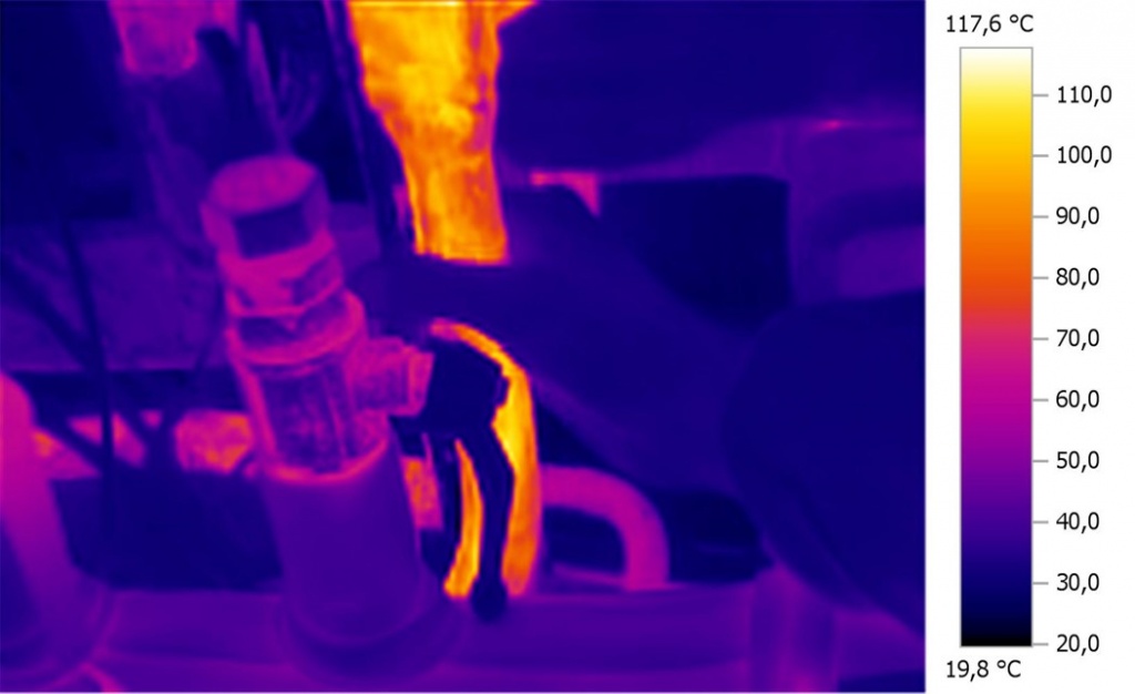
The Fluke 561 device is a partial radiation pyrometer operating in the wavelength range of 8...14 microns. Such pyrometers, by their metrological properties, approach the properties of quasi-monochromatic pyrometers, for which the methodological error of measurement is determined and can be (at temperatures up to 500 °C) from 5 to 55°With depending on the emissivity coefficient of the measuring object. Therefore, the temperature close to the actual temperature can be measured by the device only in cases when the emissivity is known in advance and is high (the coefficient is greater than 0.9). The device provides for a change in the emissivity setting (0.3; 0.7; 0.9), but the documentation for the device emphasizes that this does not guarantee an increase in measurement accuracy. Therefore, it is recommended to measure the surface temperature for each object using a thermocouple (a type K thermocouple can be connected to the device), and then by selecting the settings to achieve the best match of the results. That is, the Fluke 561 pyrometer, according to the principle of operation, can give a significant error in temperature measurement. Therefore, its main purpose is not to measure temperature, but to conveniently and quickly detect local places of heat inflows or outflows by scanning the surface. For this, the actual surface temperature is not needed in principle, it is enough that its emissivity is the same. Confirmation of this is the shooting with a thermal imager, where the hand freely holds a section of the pipe covered with liquid thermal insulation Armor, and the device shows the temperature on the surface of 110 ° C.
The SUR-25 readings differ significantly from the actual surface temperature. This is easily explained, since the temperature sensor has no contact with the surface and records the temperature of the boundary layer at a distance of 1.5 mm from the surface. The bimetallic plate faces the surface and has a width of about 3 mm, so the total thickness of the boundary layer increases to 4.5 mm. In addition, a bimetallic plate is an unreliable temperature sensor for measuring.
The IPP-2 data for a non-insulated pipeline are quite possible calculations (Table. 3) this is confirmed. The same cannot be said about the indications of IPP-2 on surfaces with thermal insulation. Calculations show that the values of heat fluxes of 306 and 409 W/m2 are not correlated with temperatures of 38 and 40°C (Table 2). For example, for existing insulation at qF = 306 W/m2 and the corresponding value of qi = 711 W/m, the surface temperature should be significantly higher than 38 °C. And if we take as a basis both qi = 711 W/ m2 and tizn = 38 ° C, then at real values of Rn it can be if the λiz will be 2 ... 3 W / (m * K), which is an order of magnitude greater than the real values of the λiz. At a surface temperature of 39.7°C (Table. 2), which is estimated above as close to reliable, and the real values of Rn and λiz (the values of the values are estimated above), the heat flux qF should be about 175 W/m2 (Table 3) (or qi = 406.8 W/m). That is, for the existing insulation, the IPP-2 readings are overestimated by about 1.7 times.
To cover the initially, the value of λiz = 0.001 W/(m *K) was included in the calculation. As the calculations showed (Table. 3), the indicators obtained in this case clearly do not correspond to the measurements, which may be due to the discrepancy between the accepted and actual values. The solution of the inverse problem under the condition t= 40 °C, which is estimated above as reliable, showed that for real t, the value of λ should be about 0.004 W/(m *K). Calculations for this value are given in Table 3. According to calculations, the qF value should be about 130 W/m2 while the IPP-2 showed 409 W/m2, that is, in this case we have an overestimation of the IPP-2 readings by 3.1 times.
The inflated readings of the IPP-2 on the surfaces of the Armor insulation can be explained as follows.
The principle of operation of the IPP-2 is complete with the PTP-9 probe.9P is based on measuring the temperature difference on the plate surfaces (according to passport data, the plate diameter is 40 mm, thickness is 2 mm). The temperature difference is measured using a tape thermocouple built into the probe plate. According to the measured temperature difference, the density of the heat flow can be determined by the formula

where λ is the thermal conductivity coefficient of the plate material (the probe passport indicates λ= 0.5 W/(m *K)); Δt is the measured temperature difference; Δl is the distance between the temperature measurement points (plate thickness).
Let's define the Δt that the device recorded when measuring, for example, qF = 306 W/m2 (Table 2)
With such temperature differences, small changes in the measurement conditions when the probe comes into contact with the surface can lead to a significant change in the measured value.
Suppose a thermocouple gives an error of 0.2 °C, then the temperature difference will be measured with an error of Δ = 0,2/1,224*100=16,3%& and with the same error we get the value of qF.
In fact, for the best of thermoelectrode materials (platinum-platinum), the permissible deviations of readings in the temperature range are 0...300 °C is 0.01 mV, which corresponds to 1.09 °C. That is, only a thermocouple can give an error that is about 89% of the measured value.
In addition, it is impossible to ensure contact on pipelines over the entire surface of the probe plate. On a rigid outer surface, the contact will be linear, on a less rigid one – partially planar. This may lead to additional measurement errors. According to the passport of the PTP-9 probe.9P The reduced measurement error is ± 5%, which corresponds to approximately 500 W/m2. That is, the permissible measurement error exceeds the measured values (Table 2).
If we ignore the absolute values of the indicators and compare different thermal insulation by heat flows, then this should be done by the values of qi. It is impossible to compare qF by heat flows, since the value of qF depends on the diameter for which it is determined. Comparison by measurement results (Table. 2) shows that the existing insulation and coating provide approximately the same heat loss from the heat line. Taking into account possible deviations of the actual source data from those taken into account in the calculations and according to the Table. 3 coatings are almost equivalent in efficiency (with some advantage of coating).
The high efficiency of the coating with a small insulation thickness consists of three components: a low value of λ, a decrease in the diameter of the outer surface, and a decrease in the radiant component of heat transfer.
For any thermal insulation of pipelines, the temperature along the insulation thickness decreases logarithmically, that is, the greatest temperature drop occurs in the layer closest to the insulated surface, and then the intensity of temperature changes decreases. For Armor coating, this is more pronounced due to the low λ. Therefore, for heat pipelines, an increase in the thickness of thermal insulation of more than 1.5 ...2 mm may not be justified. If we compare different thermal insulation only by the values of λ, then due to the nonlinear dependence of temperature changes, linear comparisons of the form cannot be carried out: if we reduce the thermal insulation by 10 times, then at the same temperature of the outer surface, the thickness of the insulation layer should be 10 times less. For example, if we theoretically increase the thickness of the coating to 5.5 mm, then according to calculations similar to those carried out above (Table. 3), at λiz = 0.004 W/(m *K) we get tizn = 26 °C.
The above allows us to draw the following main conclusions:
1) Ultrafine thermal insulation coating is a highly effective thermal insulation material. The numerical value of the thermal conductivity coefficient is 0.0012 W/(m * S). This is an order of magnitude less than that of the best thermal insulation materials, which in most cases are used in heat supply systems;
2) This material can be recommended for thermal insulation:
*sections of heat pipelines that are not currently insulated at all or are partially insulated. This will reduce fuel consumption on heat supply sources by at least 8%;
*heat pipelines and other surfaces in enclosed spaces (boiler houses, pumping substations, TRS) and aboveground heat pipelines (durability, ease of maintenance, reduction of dimensions, improvement of ecology and design, etc.);
•any heat pipes. In contrast to the widely used glass wool, the coating retains its original thermal insulation properties for a long time, which is confirmed by the operation of natural objects with coatings for 3-4 years and the results of accelerated climatic tests, which assess the durability of the coating for at least 15 years.
3) Determination of the temperature of the outer surface of thermal insulation the most reliable and reliable are the determination of temperature by touch, using a thermocouple, Elcometr 319 device, PosiTector DPM or other similar devices.
4) High coating efficiency with a small insulation thickness is achieved due to a low thermal conductivity coefficient, a decrease in the outer diameter of the insulation, a decrease in the radiant component of heat transfer.
From an environmental point of view, ultra-thin thermal insulation is safe. It does not emit substances harmful to humans and cannot harm their health.